Yet engineers and buyers still run into the same wall: how do you tell a rigid PCB apart from a flex or rigid-flex board? And once you know you need rigid, which base material and layer count actually fits your budget and application?
Rigid PCBs held 48.0% of total PCB revenue in 2025, with FR-4 accounting for 52.0% of substrate revenue that same year, according to Grand View Research's 2026 industry report. That dominance isn't an accident. It's the result of decades of manufacturing refinement.
This guide breaks down what a rigid PCB actually is, the types available, how they're made, where they show up across industries, and how to pick a manufacturing partner that won't slow down your launch.
Key Takeaways
- Rigid PCBs use solid substrates like FR-4 and cannot bend once fabricated, unlike flex or rigid-flex boards
- Single-sided through 40-layer multilayer builds support dense, high-reliability designs
- Specialty variants (heavy copper, high-Tg, high-frequency) solve specific thermal or RF challenges beyond standard FR-4
- Medical, automotive, and industrial applications demand ISO 13485 and IATF 16949-certified fabrication
- Lowest-cost, easiest-to-manufacture option when a device has space and does not need to flex
What is a Rigid PCB?
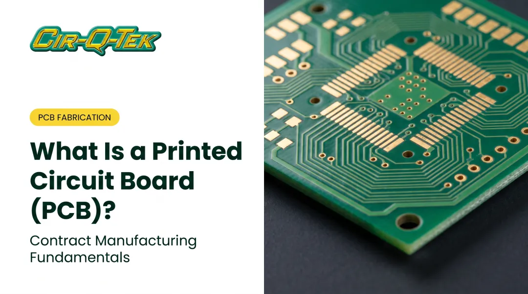
A rigid PCB is a non-flexible circuit board built on a solid substrate that holds its shape permanently. Once it's fabricated and assembled, it won't bend, twist, or flex the way a polyimide flex circuit does. You'll find rigid boards in single-layer, double-layer, and multilayer configurations, all sharing the same structural principle: a fixed form that resists distortion under normal use.
That permanence is the defining trait separating rigid from flex. A flex circuit is designed to move with a device. A rigid board is designed to stay exactly where it's installed.
Base Materials and Structure
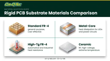
FR-4 (glass-reinforced epoxy laminate) is the default rigid PCB substrate. It delivers:
- Solid thermal resistance for typical operating environments
- Mechanical strength that holds up under vibration and handling
- Dimensional stability across manufacturing and assembly cycles
As a real-world data point, Isola's IS410 FR-4 laminate lists a glass transition temperature (Tg) of 180°C, with flexural strength around 570 MPa along the length. Numbers like these vary by manufacturer and product line, so always check the specific datasheet rather than assuming "FR-4" means one fixed spec.
Beyond standard FR-4, a few specialty substrates cover edge cases:
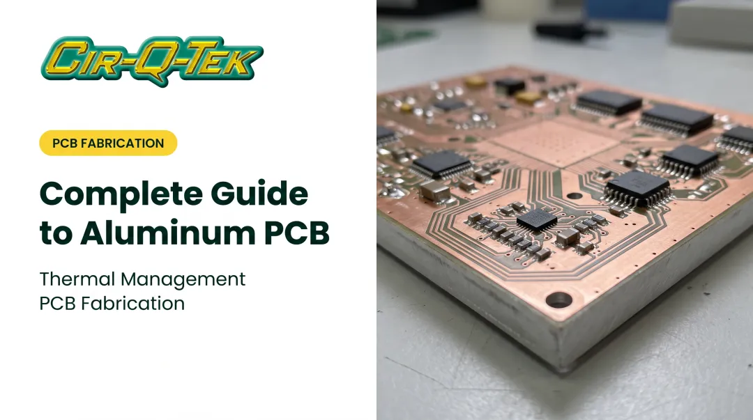
- Metal-core (aluminum or copper) boards move heat away from high-power LEDs and power conversion circuits
- High-Tg FR-4 resists softening at elevated temperatures, useful in automotive underhood or industrial environments
- Ceramic substrates (alumina, aluminum nitride) handle RF, high-voltage, and extreme-temperature designs
Key Features and Characteristics
Rigid PCBs earn their market share through a handful of practical advantages:
- Dimensional and thermal stability — the board stays flat and consistent through soldering and thermal cycling
- Strong electrical insulation between conductive layers
- High voltage/current handling when copper weight, trace design, and cooling are specified correctly
- Cost-effective mass production compared to flex and rigid-flex alternatives
Current capacity is not a fixed "amps per ounce" figure—it depends on copper cross-section, allowable temperature rise, and cooling, per IPC-2152 guidance summarized by ANSI.
- Copper thickness, solder mask type, and surface finish all affect the final board's conductivity, durability, and solderability. Cir-Q-Tek's manufacturing sources, for instance, offer HASL, lead-free HASL, ENIG, immersion silver, immersion tin, and OSP finishes, each with different tradeoffs in flatness, shelf life, and cost.
Types of Rigid PCBs
Rigid PCBs are grouped mainly by layer count, plus specialty variants built for specific electrical or thermal demands. Layer count drives circuit density and complexity; specialty variants solve niche problems standard FR-4 can't.
Single-Sided Rigid PCBs
A single-sided board has one conductive copper layer on one face of the substrate. It's the simplest, cheapest design available.
- Common in low-cost, low-density devices
- Typical uses: lighting boards, simple power supplies, basic calculators
Double-Sided Rigid PCBs
Double-sided boards carry components and traces on both faces, connected through plated through-holes.
- Roughly doubles routing density versus single-sided designs
- Common in test equipment, HVAC controls, and power monitoring systems
Multilayer Rigid PCBs
Multilayer boards stack three or more conductive layers, each separated by insulating material and laminated together into one solid structure.
- Standard choice for computers, GPS trackers, and mobile phones
- Supports far denser routing than single- or double-sided designs
Vendor capabilities vary widely. Cir-Q-Tek builds up to 40-layer multilayers through its Asian manufacturing sources, using laser direct imaging (LDI) on dense builds.
LDI writes circuit patterns directly onto photoresist with a laser instead of a phototool. That approach cuts distortion and shrinkage that film-based imaging often introduces on high-layer-count boards.
Specialty Rigid PCB Variants
Three variants address specific technical requirements standard FR-4 can't cover:
- Heavy copper PCBs: thicker copper (roughly 4–20 oz/ft², with extreme builds higher) for boards that carry substantial current
- High-Tg PCBs: laminates rated 170°C or above, versus standard FR-4 at 130–140°C, for sustained heat exposure
- High-frequency PCBs: RF-optimized materials such as Rogers RO4003C (dielectric constant 3.38 ± 0.05, dissipation factor 0.0027 at 10 GHz) for microwave and RF circuits
Rigid PCB Manufacturing Process at a Glance
The fabrication sequence follows a consistent path across the industry, regardless of layer count:
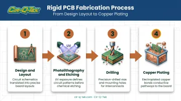
- Design and layout — engineering finalizes the circuit pattern and stackup
- Photolithography and etching — circuit patterns are imaged onto copper and unwanted copper is etched away
- Drilling — holes are cut for vias and component mounting
- Copper plating — plated holes create electrical connections between layers
Once the core structure is built, finishing steps follow:
- Solder mask — applied for electrical and environmental protection
- Surface finish — HASL, ENIG, or OSP protects exposed copper and preserves solderability
- Silkscreen — component references and identifiers are printed on
Before boards move to assembly, automated inspection catches defects early:
- AOI checks each inner layer for opens, shorts, or etching errors before lamination
- X-ray inspection verifies layer alignment and hole-to-pad registration on multilayer boards
- Electrical testing confirms the finished bare board matches the design intent
Cir-Q-Tek runs this layered inspection at its Asian fabrication sites, then performs a secondary inspection at its Pennsylvania facility before boards ship to customers.
Applications of Rigid PCB Across Industries
Rigid PCBs are the default choice anywhere a device has room for a solid board and doesn't need it to bend. Laptops, tablets, and GPS equipment rely on that solid construction for durability and dimensional stability.
Medical and healthcare devices that use rigid PCBs include:
- Diagnostic equipment, MRI systems, and patient monitors
- Tight-tolerance boards built under ISO 13485-aligned quality controls
Automotive electronics put rigid boards into:
- Control units, sensors, and infotainment systems
- High-vibration, wide-temperature environments over the vehicle lifespan
Telecommunications and industrial process control rely on rigid boards for:
- Motherboards, network equipment, and control instruments
- Stable power and signal distribution in always-on environments
Consumer, commercial, and gaming electronics are the highest-volume rigid PCB category:
- Cost efficiency and mass producibility outweigh heavy regulatory overhead
- Standard FR-4 rigid construction fits high-volume builds without flex complexity
Rigid vs. Flex vs. Rigid-Flex PCB: Key Differences
The core difference comes down to substrate. Rigid PCBs use FR-4 and physically cannot bend. Flex PCBs use polyimide so they can bend and fold into compact shapes. Rigid-flex boards combine both in one construction.
| Factor | Rigid | Flex | Rigid-Flex |
|---|---|---|---|
| Substrate | FR-4 epoxy laminate | Polyimide | Both, combined |
| Flexibility | None | High | Selective |
| Relative cost | Lowest | Higher | Highest |
| Manufacturing complexity | Simplest | Specialized bonding | Multiple lamination cycles |
| Best fit | Space-abundant, stationary designs | Compact, moving, or foldable products | Designs needing both stability and movement |
Cost and complexity rise from rigid to flex to rigid-flex. Flex and rigid-flex need specialized lamination and bonding steps, which add lead time as well as cost.
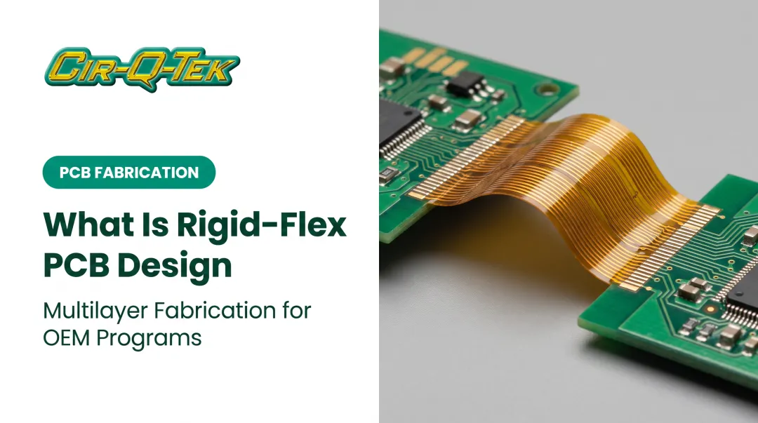
Rigid-flex PCBs combine both constructions in a single build, with rigid sections providing structural support and flexible sections routing around corners or moving parts. They are well suited to wearables, foldable devices, and compact medical instruments that need stability in some zones and flexibility in others.
When should you choose rigid over flex or rigid-flex? Choose rigid when:
- The project is cost-sensitive
- The enclosure has adequate internal space
- The board never needs to bend in use
That covers the vast majority of electronic designs on the market today.
Choosing the Right Rigid PCB Manufacturing Partner
Picking a fabricator isn't just about price per board. A few factors matter more than they might seem at first glance.
Certifications should match your industry's regulatory demands:
- ISO 9001 for general quality management
- ISO 13485 for medical device projects
- IATF 16949 for automotive-grade reliability
Ask for the certificate scope and expiration date directly, not just a logo on a website.
Quick-turn prototyping capability matters when time-to-market is tight. Cir-Q-Tek, for example, builds rigid PCB prototypes in as little as 3 days and ships within 2, giving engineering teams a fast feedback loop before committing to production volumes.
One-stop manufacturing simplifies supply chain management. Juggling separate vendors for boards, assembly, and machined parts adds friction. A partner that handles PCB fabrication, turnkey PCBA, and precision CNC machining under one roof cuts that overhead and reduces the relationships you manage.
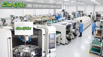
Cir-Q-Tek's model pairs offshore fabrication pricing through its Shenzhen-based sourcing network with domestic quality inspection at its Pennsylvania facility. That keeps cost down without sacrificing oversight.
Frequently Asked Questions
What is a rigid PCB?
A rigid PCB is a non-flexible, solid-substrate circuit board, typically made from FR-4, that maintains a fixed shape and supports components with through-hole or surface-mount soldering.
What is the difference between rigid and flex PCB?
Rigid PCBs use stiff FR-4 material, cost less, and are easier to manufacture. Flex PCBs use bendable polyimide, cost more, and suit compact or dynamic applications where the board needs to move.
What is the most common rigid PCB base material?
FR-4 is the standard rigid PCB substrate, chosen for its mechanical strength, thermal resistance, and dimensional stability across manufacturing and assembly cycles.
How many layers can a rigid PCB have?
Rigid PCBs range from single-layer designs to advanced multilayer builds up to 40 layers. Layer count depends on circuit complexity, routing density, and available space.
Are rigid PCBs cheaper than flex PCBs?
Generally, yes. Rigid PCBs cost less to manufacture due to simpler processes. Flex and rigid-flex boards cost more upfront but can reduce assembly costs in space-constrained designs.
What industries use rigid PCBs the most?
Medical devices, automotive, telecommunications, industrial process control, and consumer electronics are the heaviest users of rigid PCB technology across the market.