Milling a board yourself feels great for simple two-layer circuits. But push past that into multilayer stacks, fine-pitch parts, or anything headed for a regulated industry, and DIY milling hits a wall fast.
This guide walks through how PCB CNC milling actually works, how it compares to breadboards and chemical etching, the real DIY workflow from CAD to G-code, and — critically — how to recognize the point where a professional prototyping partner becomes the smarter move.
Key Takeaways
- Isolation milling cuts copper away with a spinning bit, skipping the hazardous chemicals used in etching
- Desktop mills can't produce plated through-holes, solder mask, or silkscreen — those require separate processes
- Multilayer boards, 0201/01005 parts, and BGA packages push most designs past DIY capability
- Professional quick-turn fabrication now delivers prototypes in days, not weeks, closing the speed gap DIY milling once owned
What Is PCB CNC Milling?
PCB CNC milling, often called isolation milling, is a subtractive manufacturing process. A CNC machine reads a digital layout file, then cuts away copper from a blank, copper-clad board to leave behind traces, pads, and drilled holes.
Unlike etching, which dissolves unwanted copper in a chemical bath, milling removes it mechanically with a rotating cutting tool.
The Core Components
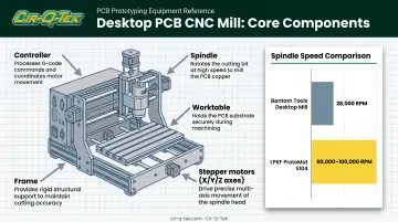
A typical desktop PCB mill includes:
- Controller – interprets G-code and drives the machine's motion
- Spindle – holds and spins the cutting bit; speed and runout directly affect cut quality
- Worktable – holds the copper-clad board flat and stationary during the cut
- Stepper motors – move the spindle along the X, Y, and Z axes with precision
- Frame – the rigid structure that keeps everything aligned under cutting load
Spindle speeds vary significantly by machine. Bantam Tools' desktop mill runs around 28,000 RPM, while LPKF's ProtoMat S104 documents speeds between 60,000 and 100,000 RPM. Higher speeds generally support cleaner, smaller cuts, but the number alone doesn't guarantee precision: bit geometry, feed rate, and depth control matter just as much.
Why "Isolation" Milling?
Instead of stripping all excess copper off the board (which would take far longer), isolation milling cuts narrow channels around each trace and pad. The remaining copper on either side of that channel is electrically isolated, forming your circuit. That makes it much faster than full-field copper removal—and a practical fit for engineering labs and prototype teams that need boards without a chemical etch process.
PCB Milling vs. Breadboards vs. Chemical Etching: Choosing the Right Method
Every prototyping method trades speed, cost, and durability differently. Picking the wrong one for your project stage wastes time you don't have.
Breadboards: Fine for Quick Tests, Risky Beyond That
Breadboards are unbeatable for five-minute sensor tests or verifying a chip's pinout. But push component count up, and things get fragile fast.
The problem is parasitic behavior. Breadboard sockets and jumper wires introduce resistance, inductance, and capacitance that aren't present in a real circuit. Analog Devices notes that these parasitics can meaningfully degrade high-speed and precision circuits, recommending shorter interconnects for anything performance-sensitive.
So which is better, PCB or breadboard? For anything beyond a quick functional check, a milled or fabricated PCB wins. It gives you:
- Permanent, production-representative connections
- A proper ground plane instead of floating jumper loops
- Repeatable results you can hand off or revise with confidence
Milling vs. Chemical Etching
Both methods remove copper to form circuit patterns, but the process and the risk differ sharply.
Chemical etching typically uses ferric chloride. It works, but it's not casual chemistry. MG Chemicals' safety data sheet for its ferric chloride etchant flags serious eye damage, skin irritation, and aquatic hazards.
You need chemical-resistant gloves, eye protection, and controlled disposal—not a process you want open on a crowded bench.
CNC milling skips that entirely. No baths, no fumes, no spill kits. It also handles isolation cutting and drilling in a single machine setup, while etching still requires a separate manual drilling step, one that's notoriously prone to misaligned holes when done by hand.
Etching does still have an edge in one area: ultra-fine resolution on some designs, since chemical dissolution isn't limited by bit diameter the way mechanical cutting is.
Quick Comparison
| Method | Turnaround | Cost | Durability | Best For |
|---|---|---|---|---|
| Breadboard | Minutes | Lowest | Temporary, fragile | Quick functional tests |
| Chemical Etching | Hours | Low (consumables) | Moderate, no plating/mask | Fine-trace single-sided boards |
| DIY Milling | Hours | Low (after equipment) | Moderate, no plating/mask | Simple proof-of-concept boards |
| Professional Fabrication | Days | Moderate per board | Production-grade | Multilayer, fine-pitch, regulated designs |
That "days" figure matters more than it used to. A 2024 engineering industry overview reports rigid quick-turn PCB service available in as little as 24 hours, with roughly a week typical for flex or rigid-flex boards.
That is a real change from the multi-week outsourced runs that once made DIY milling the only fast option.
The DIY PCB Milling Workflow: CAD, CAM & Mill
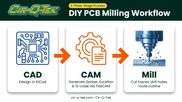
Getting from an idea to a milled board follows three stages: CAD, CAM, and Mill. Skip a step or misconfigure one, and you'll spend more time troubleshooting than milling.
CAD — Design the board. Build your schematic and layout in a tool such as KiCad. Autodesk EAGLE is being phased out, with support ending June 2026 in favor of Fusion Electronics, so factor that in if you are choosing software now.
CAM — Generate machine instructions. KiCad exports Gerber files for copper layers and Excellon files for drill data. Tools like FlatCAM convert those files into G-code your mill can execute.
Mill — Cut the board. The CNC runs the G-code to isolate traces, drill holes, and cut the board outline.
Design Rules You Must Adjust
Default design-rule settings from PCB service shops will break on a desktop mill. Before exporting, adjust these:
- Clearance – increase spacing between traces to account for bit width and cut tolerance
- Minimum track width – Bantam Tools recommends using the widest traces your layout allows
- Annular ring sizing – aim for at least 6 mils around through-holes and vias to avoid breakout
Even a flawless DIY setup has hard limits. Desktop mills can't produce solder mask, silkscreen, or plated through-holes. Those need separate chemical or lamination processes a mill alone does not perform.
Advantages & Limitations of Desktop CNC Milling for Prototyping
Desktop milling belongs in a prototyping toolkit, but it is not a universal solution.
What It Does Well
- No hazardous chemicals — safe to run in an office or lab setting
- Same-day iteration — redesign, re-mill, and test again within hours
- Fit and function checks — validate form and connectivity before a paid production order
Where It Falls Short
- No plated through-holes or solder mask — vias need manual wire links, and bare copper is exposed
- Struggles with fine-pitch or multilayer designs — registration between layers isn't reliable
- Accuracy drifts with board flatness — a slightly bowed blank can leave copper uncut or over-cut in spots
Desktop milling fits early proof-of-concept work: boards you are testing for basic function. It is a poor fit for regulated product lines or designs packed with BGAs and high pin-count parts.
When Professional PCB Prototyping Outperforms DIY Milling
There's a clear tipping point where DIY milling stops being the fast option and starts being the bottleneck.
The Wall DIY Hits
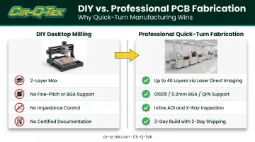
- 4+ layer boards — desktop mills can't manage layer registration reliably
- Fine-pitch components — 0201, 01005, BGA, QFN packages need tolerances mills don't hit
- Tight electrical tolerances — impedance control and repeatable trace geometry aren't achievable
- Certified documentation — regulated industries need traceability a home setup can't generate
Professional Quick-Turn Closes the Speed Gap
This is the part DIY milling used to own exclusively: speed. Cir-Q-Tek's quick-turn PCB prototype service builds boards in 3 days and ships in 2, putting a validated, production-representative prototype on your dock nearly as fast as milling one at your desk, without the same capability limits.
That speed comes paired with capability desktop mills simply don't have:
- Multilayer PCBs up to 40 layers — laser direct imaging avoids the distortion and registration drift common with traditional photolithography
- 01005, 0.2mm BGA, QFN, and CSP packages — sub-3-mil trace and space tolerances no desktop bit can replicate
- Inline AOI and X-ray inspection on every SMT line — catches solder voids and hidden BGA joint defects a visual check would miss
Regulated Industries Change the Equation Entirely
If your board is headed into a medical device or an automotive system, certification isn't optional. ISO 13485 governs medical device manufacturing traceability, and IATF 16949 covers automotive quality requirements.
Both standards demand documented identification and traceability records that a home CNC setup has no mechanism to produce. At that point, DIY milling stops being a valid option, regardless of skill level.
How to Choose the Right PCB Prototyping Partner
Once you've decided to move beyond DIY, not every fabrication partner offers the same depth of capability.
Evaluation Criteria That Actually Matter
- Demand a specific turnaround number, not a vague estimate
- Ask for documented layer-count and tolerance maximums, not marketing copy
- Require ISO 9001 at minimum; add ISO 13485 and IATF 16949 for medical or automotive work
- Confirm AOI and X-ray run inline, not as spot checks
Questions Worth Asking Before You Commit
- What's your defect replacement policy if a board doesn't match the fabrication data submitted?
- Do you offer one-stop services (PCB, PCBA, and CNC machining) so I'm not juggling multiple vendors as I scale?
- Can you support both prototype quantities and volume production without re-quoting from scratch?
Why Dual-Presence Suppliers Reduce Risk
First-time outsourcers face a real communication risk when working with an overseas factory directly. Suppliers with both domestic and offshore presence close that gap. Cir-Q-Tek's Bristol, Pennsylvania headquarters, paired with its Shenzhen office and bilingual staff, is built for that model: offshore pricing with a domestic point of contact. That matters most on your first order, when you don't yet know what questions to ask.
Frequently Asked Questions
What is a PCB CNC machine?
A PCB CNC machine is automated equipment that mills, drills, and routes PCB material based on a digital design file. It produces precise, repeatable board fabrication without manual cutting.
Which is better, PCB or breadboard?
Breadboards suit quick, simple, temporary tests where you're still exploring a design. PCBs — milled or professionally fabricated — offer the reliable, permanent connections needed for anything beyond basic prototyping.
How long does PCB CNC milling take compared to chemical etching?
Milling is typically faster and safer since it skips the chemical dip and separate drilling step etching requires. That said, setup and design-rule checks still take real time regardless of method.
Can CNC milling produce multilayer or plated-through-hole PCBs?
Desktop mills generally can't add plating or manage multiple layers reliably. That's precisely why complex, multilayer, or plated-hole boards move to professional fabrication once a design matures past proof-of-concept.
What is the difference between PCB milling and PCB routing/depaneling?
Isolation milling creates the actual circuit pattern by removing copper around traces and pads. Routing or depaneling is a separate step that cuts finished boards apart from a larger manufacturing panel.
How much does professional PCB prototyping typically cost compared to DIY milling?
DIY milling has a lower per-board cost for simple designs once you've bought the equipment. But professional quick-turn prototyping often costs less overall once you factor in complexity, rework, and the time lost to failed iterations.