That's the reality driving aerospace PCB assembly. Mission-critical systems like autopilot and navigation demand near-zero failure tolerance, while non-critical systems, such as cabin lighting controls, still need to fail safely rather than cascade into bigger problems.
This guide covers what aerospace PCB assembly actually involves: the process, the materials, the standards that govern it, the challenges manufacturers face, and how to vet a manufacturing partner before you commit a program to one.
Key Takeaways
- Aerospace PCB assembly builds boards that survive extreme vibration, temperature swings, and radiation in flight and space.
- It adds specialized steps beyond commercial work: traceable sourcing, ultra-fine-pitch placement, multi-stage inspection, and conformal coating.
- AS9100 certification and full supply chain traceability are standard requirements for aerospace-grade programs.
- A partner with proven inspection tech and quick-turn capability cuts risk and shortens time-to-market.
What Is Aerospace PCB Assembly?
Aerospace PCB assembly is the end-to-end process of designing, fabricating, populating, and testing printed circuit boards built for aircraft, satellites, spacecraft, and defense systems. The work goes well beyond soldering parts onto a board. Engineers build assemblies that must survive conditions commercial electronics never encounter.
Mission-critical components include flight control computers, autopilot systems, and navigation modules. If one of these fails mid-flight, the consequences are immediate. Non-critical components, like seat adjustment controls or cabin lighting, matter less in the moment, but they still need to fail safely. A short circuit in a seat control shouldn't take down an adjacent power bus.
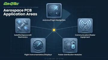
Primary applications span:
- Avionics and flight navigation systems
- Communication and radar equipment
- Power distribution modules
- Flight instrumentation and displays
- Satellite and spacecraft electronics
Why Commercial Practices Fall Short
Standard commercial PCB assembly is built around cost and speed. Aerospace assembly is built around multi-decade survivability in environments commercial boards rarely see: vacuum, extreme altitude, and sustained high-speed flight.
Demand for this level of engineering isn't slowing down. The global avionics market is projected to grow from $56.22 billion in 2025 to $82.33 billion by 2030, a 7.9% CAGR, according to MarketsandMarkets. That growth touches navigation, flight management, and power/data systems, all of which depend on assemblies that meet a much higher bar than a typical consumer product board.
The Aerospace PCB Assembly Process, Step by Step
Component Selection and Sourcing
Every part gets rated for extreme temperature, vibration, and radiation exposure before it's approved. Full traceability back to authorized distributors is mandatory—it keeps counterfeit or gray-market components out of the supply chain. A single unverified part can invalidate an entire build.
PCB Design and Layout
Engineers address signal integrity, controlled impedance, thermal paths, and EMI/RFI shielding before fabrication begins. This front-loaded design work catches problems on paper, where they're cheap to fix, instead of on a finished board, where they're not.
Precision Component Placement
Pick-and-place equipment handles surface-mount parts, but aerospace boards push the limits. Ultra-fine-pitch components like 01005 passives, BGAs, and QFNs require tighter placement tolerances than commercial electronics typically demand, sometimes down to spacing measured in fractions of a millimeter.
Through-Hole Assembly and Soldering
High-power or ruggedized connections often still rely on through-hole construction. These joints offer mechanical strength that surface-mount alone can't match, critical when boards face repeated shock loading.
Multi-Stage Inspection and Testing
Aerospace assemblies typically go through several inspection layers:
- Automated Optical Inspection (AOI) verifies placement and solder joints
- X-ray inspection catches voids hidden under BGAs and QFNs
- In-Circuit Testing (ICT) checks performance against customer-defined electrical parameters
- Thermal and vibration testing matches the platform's actual flight or launch profile
Exact inspection scope depends on the contract and IPC class specified, not a one-size-fits-all checklist.
Conformal Coating and Final Finishing
A protective coating shields the board from moisture, chemicals, and salt fog, conditions common in both flight and ground handling environments. It's typically the final step before the board leaves the assembly floor.
Design and Material Considerations for Harsh Environments
Materials That Survive Heat and Stress
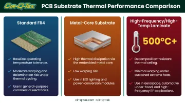
High-temperature laminates and metal-core substrates, including aluminum and copper cores, let boards survive near-engine heat and repeated thermal cycling without warping or delaminating. Some high-frequency laminates carry decomposition ratings above 500°C, though actual continuous-use limits depend on the specific application and should always be confirmed against the manufacturer's data sheet.
Radiation: Two Different Problems
Atmospheric RF interference and ionizing space radiation are not the same hazard, and they don't get the same fix.
- RF/EMI (non-ionizing): Shielding and layout choices manage interference from radios, radar, and onboard electronics.
- Ionizing radiation (space): Cosmic radiation and high-energy particles can degrade components at the semiconductor level.
NASA notes that shielding helps against cumulative dose but has limited effect on single-event upsets from cosmic rays. Part selection and circuit design matter as much as physical shielding.
Vibration and Shock Resistance
Solder joint reinforcement, component staking, and mechanical bracing all reduce fracture risk during takeoff, turbulence, or launch. A joint that looks fine on inspection day can still fail after 500 flight hours of vibration if it wasn't reinforced correctly.
Weight, Space, and Density
Aerospace programs push hard toward miniaturization. Packing more functionality into less board space, without adding weight, usually means going to higher layer counts.
Some manufacturers, including Cir-Q-Tek, now offer multilayer PCBs up to 40 layers using laser direct imaging (LDI), which avoids the distortion and positional error that traditional imaging can introduce at high layer counts.
At those densities, material spec precision matters as much as layout. Aerospace tolerances—down to exact alloy mixes—are far stricter than typical commercial PCB specs, and that precision demands double inspection, not a single pass.
Key Challenges and Standards Compliance in Aerospace PCB Manufacturing
Aerospace PCB programs face the same core physical challenges:
- Temperature extremes across operating environments
- Vibration and shock during launch and flight
- EMI/RFI interference in dense avionics systems
- Component obsolescence over decades-long product lifecycles
Standards compliance is where most of the real scrutiny happens.
| Framework | What It Covers |
|---|---|
| AS9100 | ISO 9001 plus risk, configuration, and key-characteristics controls (SAE International) |
| Nadcap | Industry-managed accreditation for special processes such as heat treating and welding |
| IPC / ECSS | Acceptance criteria, workmanship standards, and environmental qualification |
Prime contractors like Boeing and Lockheed Martin flow these requirements down through their supply chains. They typically require accredited QMS certification plus Nadcap approval for special processes named in the contract.
What regulators scrutinize most:
- Complete documentation and record retention
- First article inspection results
- Full material traceability back to approved sources
- Unauthorized component substitution — treated as a major compliance failure, not a minor deviation
How to Choose the Right Aerospace PCB Assembly Partner
Not every manufacturer that builds precision electronics is set up for aerospace work. Here's what actually separates a qualified partner from a risky one.
Evaluate partners against these checks:
- Quality certifications: ISO 9001 is the baseline. ISO 13485 (medical) or IATF 16949 (automotive) experience shows the documentation discipline aerospace work needs—even before AS9100 is on the table.
- Inspection infrastructure: Inline AOI and X-ray on SMT lines catch solder voids and misalignment before they become field failures. No floor demo is a red flag.
- Prototyping speed and turnkey scope: Confirm the partner can take you from design review through prototype and into production without splitting the job across multiple vendors.
- Traceability and defect policies: Parts should come from approved sources, with non-compliant components replaced at no extra cost.

Cir-Q-Tek maps to several of these checks. Its facilities hold ISO 9001, ISO 13485, and IATF 16949 certification, and its SMT lines run inline AOI and X-ray inspection.
It also builds with ultra-fine components down to 01005 passives and 0.2 mm BGA spacing. Quick-turn prototypes ship in roughly five days (3 to build, 2 to ship), supported by a dual U.S.–Shenzhen office model that pairs domestic responsiveness with offshore pricing.
For programs that need AS9100-specific certification or Nadcap-accredited special processes, confirm current certification scope with any manufacturer before you award the work.
Frequently Asked Questions
What is aerospace PCB assembly?
Aerospace PCB assembly is the design, fabrication, component placement, and testing of printed circuit boards built to aerospace-grade standards for aircraft, satellites, and spacecraft systems.
How are aerospace PCBs assembled?
The process includes traceable component sourcing, precision SMT and through-hole placement, soldering, multi-stage inspection (AOI and X-ray), and conformal coating for environmental protection.
How much does aerospace PCB assembly cost?
Cost varies based on layer count, component density, certification requirements, and testing scope. Request a detailed quote rather than relying on a fixed number, since programs differ widely.
What certifications should an aerospace PCB assembly manufacturer have?
AS9100 is the industry benchmark, built on an ISO 9001 foundation. IPC Class 3 workmanship standards and documented counterfeit-parts controls are also commonly expected for flight hardware.
What is the difference between AS9100 and ISO 9001?
AS9100 incorporates all of ISO 9001's requirements and adds aerospace-specific elements, including risk management, configuration control, and counterfeit parts prevention.
How long does it take to build aerospace PCB prototypes?
Timelines depend on design complexity and component availability. Some manufacturers, like Cir-Q-Tek, offer expedited quick-turn options, such as a 3-day build and 2-day ship, for faster iteration.