Introduction
A smartwatch bends around your wrist. An MRI machine's imaging coil twists into a housing. A foldable phone hinges open a thousand times a week. None of these devices tolerate a purely rigid circuit board, and none can rely on a purely flexible one either — they need both, working as one.
That's the gap rigid-flex PCB design fills. It combines rigid FR-4 sections with flexible polyimide layers into a single interconnected structure, eliminating the connectors and ribbon cables that traditionally link separate boards.
This article breaks down what rigid-flex actually is, how it differs from standard rigid and flex boards, the design considerations engineers can't skip, where it delivers the most value, and what to look for in a manufacturing partner.
Key Takeaways
- Rigid-flex merges FR-4 and polyimide into one continuous circuit, cutting connector count and failure points
- Designs are inherently three-dimensional, demanding careful bend radius and stack-up planning
- Static builds flex once during install; dynamic builds must survive hundreds of thousands of cycles
- Medical, aerospace, automotive, and consumer electronics are the leading adopters
- Manufacturer certifications and design collaboration prevent costly re-spins
What Is Rigid-Flex PCB Design?
Rigid-flex PCB design is the practice of laminating flexible circuit substrates, typically polyimide, together with rigid board sections, usually FR-4, into one continuous, interconnected structure. Instead of two separate boards joined by a connector, you get a single assembly that transitions seamlessly from rigid to flexible where the application demands it.
The construction relies on plated through holes and vias that stitch the rigid and flexible layers together internally. That's the core advantage: electrical and mechanical connections stay inside the board rather than depending on external hardware that can loosen, corrode, or fail under vibration.
Materials That Make It Work
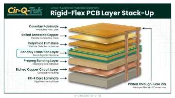
Each layer type plays a specific role:
- FR-4 core/prepreg — provides structural strength in rigid zones and supports components, connectors, and dense routing
- Polyimide film with rolled copper — delivers flexibility and thermal resistance in bend zones
- Bondply and coverlay — insulate and protect flex-area copper from moisture and abrasion
- No-flow prepreg — bonds layers without resin migrating into flex regions during lamination
Copper choice matters too. Rolled-annealed (RA) copper is preferred in flex zones for its ductility, while electrodeposited (ED) copper is more common in rigid sections for strength and cost efficiency. Getting this material pairing wrong is one of the fastest ways to end up with cracked traces down the line.
Most rigid-flex builds run 4, 6, or 8 layers, though advanced designs scale well beyond that. Cir-Q-Tek, for instance, supports multilayer PCB fabrication up to 40 layers, using laser direct imaging (LDI) to maintain layer-to-layer accuracy as complexity climbs. That accuracy matters once you're stacking blind and buried vias across a dozen or more layers.
Static vs. Dynamic Rigid-Flex Applications
Not every flex zone works the same way, and the distinction shapes material and design choices from day one.
- Static (flex-to-install) — the flex section bends once, or a handful of times, during assembly, then stays put for the product's life. Think of a flex tab folded to fit a housing.
- Dynamic — the flex area is engineered to bend continuously, sometimes hundreds of thousands of cycles, throughout normal operation. Foldable devices and robotic joints fall into this category.
The intended flex type drives copper selection, coverlay thickness, and bend radius requirements before a single trace is routed. Design for static conditions and apply it to a dynamic use case, and you're looking at premature trace fatigue.
Rigid-Flex vs. Rigid vs. Flex PCBs: What's the Difference?
Rigid PCBs are solid laminate with no bend capability. Flex circuits bend and fold freely. Rigid-flex laminates both into one continuous stackup.
Choosing between them comes down to space, motion, and how much complexity you're willing to pay for upfront.
| Board Type | Flexibility | Cost | Best For |
|---|---|---|---|
| Rigid PCB | None | Lowest | Space-abundant designs, simple enclosures |
| Flex PCB | High | Moderate | Dynamic bending, tight spaces, lightweight builds |
| Rigid-Flex | Combined | Highest per unit | Complex 3D packaging, high reliability needs |
Rigid-flex carries the highest board-level price of the three. Industry cost analysis puts a typical rigid-flex hybrid at roughly seven times the cost of an equivalent rigid board, or two to three times the cost of a comparable flex circuit with stiffeners. That's a meaningful premium, and it shouldn't be waved away.
When Rigid-Flex Actually Pays Off
The math changes once you account for the full assembly, not just the bare board. Rule of thumb: when a design would otherwise require five or more separate rigid boards connected by flex cables and connectors, an integrated rigid-flex build usually wins on both reliability and total cost.
Why? Because rigid-flex removes:
- Discrete connectors and their associated failure points
- Cable assembly labor and routing constraints
- Separate test cycles for boards, connectors, and cable joints
- Extra package volume needed to accommodate connector hardware
So while the per-unit board price is higher, total system cost (parts, labor, test, and field reliability combined) often comes out ahead once you cross that multi-board threshold.
Key Design Considerations for Rigid-Flex PCBs
Rigid-flex is a 3D design problem. Skipping any of the following steps tends to show up later as a field failure or a re-spin.
Material selection. Match FR-4/polyimide combinations to the application's actual operating conditions: thermal cycling, chemical exposure, and mechanical stress. A material pairing that works fine in a consumer device can fail fast in an under-hood automotive environment.
Layer stack-up planning. Balance electrical performance against mechanical strength across the transition zones where rigid meets flex. These transitions are where most manufacturability problems originate.
Bend radius calculation. Too tight a radius risks trace cracking and signal degradation over repeated flex cycles. Guidance varies by source, but a common benchmark from manufacturer documentation suggests static bends of roughly 6x material thickness for single layers, scaling to 24x for multilayer constructions, while dynamic applications may require radii around 100x finished thickness.

Treat these figures as starting points, not universal law. Your fabricator's specific process will refine the number.
Component placement and trace routing. Keep components on rigid sections. Mounting anything on a flex zone stresses solder joints every time the board bends. Route traces perpendicular to the bend axis where possible, and taper them into pads to reduce stress concentration.
Reliability details that pay off:
- Add teardrops at through-holes to reduce trace lifting
- Round corners in flex zones instead of using sharp 90-degree bends
- Leave adequate distance between the rigid-flex transition and the actual bend point
Bring Your Manufacturer In Early
None of the above matters if the fabricator can't build it. Involving the PCB manufacturer's engineering and CAM team during the design phase, not after Gerbers are locked, catches stack-up or tolerance issues before they become expensive production problems.
Cir-Q-Tek's CAD and CAM support helps flag registration or lamination conflicts while there's still time to adjust the design.
Benefits and Applications of Rigid-Flex PCB Design
The appeal of rigid-flex comes down to fewer parts and fewer places for something to go wrong.
Core benefits:
- Space and weight savings from eliminating connectors and cables
- Improved reliability through fewer solder joints
- Three-dimensional design freedom for tight or irregular enclosures
- Better resistance to vibration, shock, and thermal stress than connector-based assemblies
That last point isn't theoretical. One documented aerospace case involved a weapon-system motherboard that failed after just one or two missions because vibration tore its flexible circuits. A 10-layer rigid-flex redesign, with tear-restraint tabs and rigid terminations, then completed thousands of sorties without failure.
Where Rigid-Flex Shows Up
- Medical devices — MRI/CT equipment, wearable monitors, implantable devices where space and reliability both matter
- Automotive electronics — control modules exposed to vibration and thermal cycling
- Aerospace/defense — systems where connector failure isn't an option
- Telecom equipment — dense enclosures with tight packaging constraints
- Consumer electronics — foldable phones and hinged laptops built for repeated open-close cycles
Global Market Insights valued the rigid-flex PCB market at $22.1 billion in 2023, projecting a 10.9% CAGR through 2032 to reach $55.6 billion. That growth tracks the push toward smaller, more reliable, more densely packaged electronics across the industries above.
Choosing the Right Rigid-Flex PCB Manufacturing Partner
Rigid-flex punishes manufacturing shortcuts. Fine-pitch components, tight registration tolerances, and multi-material lamination leave little room for error, so partner selection matters more here than with a standard rigid board.
What to evaluate:
- Quality certifications: ISO 9001 as a baseline, ISO 13485 for medical applications, IATF 16949 for automotive programs
- Inline inspection: AOI and X-ray capability to verify solder joints on components like BGAs and QFNs, where defects hide beneath the package
- Fine-pitch experience: proven handling of 01005 passives, 0.2mm BGA pitch, and tight-tolerance builds typical of rigid-flex assemblies
- Quick-turn prototyping: the ability to catch design issues fast, before committing to full production

Cir-Q-Tek's dual-office model is built around this exact need. Headquartered in Bristol, PA, with an operational office in Shenzhen, China, the company pairs domestic project support and quality inspection with offshore manufacturing pricing. Bilingual staff translate complex rigid-flex specifications (blind/buried vias, laser-drilled holes down to .0039", fine line/spacing to .0025"/.0025") accurately between customer and fabricator.
Prototype samples typically build in three days and ship in two. Production orders follow in 10 days to four weeks depending on complexity.
If you're weighing rigid-flex against a multi-board connector assembly, or you have a stack-up that needs a second set of eyes before it goes to production, Cir-Q-Tek's team can walk through the specifics with you.
Frequently Asked Questions
What is a rigid-flex PCB?
A rigid-flex PCB is a hybrid board combining rigid FR-4 sections with flexible polyimide layers laminated into one interconnected circuit. This eliminates the need for separate connectors and cables between boards.
What are flex PCBs used for?
Flex PCBs are common in wearables, foldable electronics, cameras, and medical devices. They fit well when you need a lightweight, bendable connection in a tight space.
How many layers does a rigid-flex PCB typically have?
Most rigid-flex builds use 4, 6, or 8 layers. Advanced designs with high circuit density can scale well beyond that. Cir-Q-Tek, for example, supports builds up to 40 layers.
What is the minimum bend radius for a rigid-flex PCB?
It depends on flex layer thickness, layer count, and copper type. Manufacturers typically provide guidelines ranging from 6x to 24x material thickness for static bends (higher for dynamic flexing) to prevent trace cracking.
Is rigid-flex PCB design more expensive than rigid PCB design?
Per-unit cost is higher, sometimes several times that of an equivalent rigid board. But total assembly cost can come out lower once you factor in eliminated connectors, cables, and assembly labor.
What industries rely most on rigid-flex PCBs?
Medical devices, aerospace/defense, automotive, and consumer electronics lead adoption. Each industry values the reliability and space savings rigid-flex delivers over connector-based alternatives.