Low-volume manufacturing runs are common practice in medical device development, where concepts often get tested in pilot markets or clinical trials before scaling up, according to ASME. That same logic applies across automotive, telecom, and industrial sectors.
Here's the problem: many engineering teams treat CNC prototyping as "just cutting a part." That mindset skips over the process sequence — and skipping it leads to poor tolerancing decisions, expensive redesigns, and blown deadlines. This guide breaks down exactly how CNC prototype machining works, stage by stage.
Key Takeaways
- CNC prototype machining cuts a functional, production-intent part directly from a CAD model using computer-controlled tools
- The process moves through four stages: programming, machining execution, in-process control, and final inspection
- Unlike 3D printing, it delivers production-grade materials and tighter dimensional consistency
- Programming and fixturing setup — not the actual cutting — usually eat up the most time on a one-off part
- Picking a machining partner who understands the full sequence cuts down on rework and missed deadlines
What Is CNC Prototype Machining?
CNC prototype machining uses computer numerical control subtractive machining to produce a low-volume or one-off part straight from a CAD model, so teams can validate a design before mass production. It's how engineering teams get a real part that fits, functions, and behaves like the production version before committing to molds, tooling, or a full manufacturing run.
That validation step matters. A part that looks correct on screen can fail in ways a screen never reveals: threads that don't seat, walls that flex under load, tolerances that stack up wrong across an assembly.
CNC Prototyping vs. Production Machining vs. 3D Printing
CNC prototype machining is easy to confuse with two related processes:
- Not standard production machining: the cutting mechanism is the same, but prototype work runs single parts or small batches rather than repeating the same cycle thousands of times
- Not additive manufacturing: 3D printing builds parts layer by layer; CNC machining removes material from a solid block or bar until the part emerges
Despite additive manufacturing's growth, CNC remains the default when a part needs production-grade material, tight tolerances, or has to survive load-bearing testing. Protolabs notes that CNC-machined parts offer isotropic mechanical and thermal behavior (consistent performance in every direction), while 3D-printed parts can behave differently depending on print orientation.
Three processes fall under the CNC prototyping umbrella:
- CNC milling: a rotating cutter removes material from a fixed workpiece; best for pocketed, contoured, or non-round geometries
- CNC turning: the workpiece rotates against a fixed tool; suited to shafts, bushings, and other cylindrical parts
- EDM: uses electrical discharge to remove conductive material; reserved for hard metals or intricate cavities where standard cutting tools can't reach
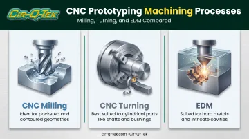
The CAD-to-cut workflow stays consistent across all three. Toolpath strategy and setup, however, shift based on part geometry.
How Does CNC Prototype Machining Work?
CNC prototype machining runs through a defined sequence of stages, not a single cutting operation. Each stage shapes how accurate and usable the final part turns out to be. Skip a step, and the downstream cost usually shows up later, when it's more expensive to fix.
Initiation: Design and Programming
Every prototype starts with a CAD model and a design-for-manufacturability (DFM) review. This review is engineer-driven, not automated. A person looks at the geometry and flags anything that will be difficult or expensive to machine.
Once the design clears DFM, CAD data converts into CAM toolpaths. These toolpaths contain:
- G-code: instructions that control tool movement
- M-code: commands that control machine functions like coolant flow or spindle start/stop
Together, G-code moves the machine while M-code controls what happens around that movement.
Programming and fixturing setup, not the actual cutting, are usually the largest time investment on a one-off prototype. One documented case from SME found that adding a programming step took about 1.5 times longer upfront, but cut later cycle time and setup time by roughly 25% and improved accuracy by avoiding repeated refixturing.
Material sourcing can stretch lead time further when a required alloy or plastic grade is not already on hand.
Core Operation: Machining Execution
This is where the cutting happens. A tool removes material from a solid block or bar of stock, following the programmed toolpath, shaping the prototype from the outside in.
Multi-axis machines (3, 4, or 5-axis) sequence pockets, profiles, and delicate features in an order that keeps the workpiece stable as material comes off. Higher axis counts can reach angles a 3-axis machine can't, often reducing the number of setups a complex part requires.
Three variables determine what tolerance and finish you'll actually get:
- Cutting speed: too fast, and tool wear or heat distorts the cut
- Tool selection: the wrong tool geometry limits achievable detail
- Axis control: more axes reduce repositioning, which reduces error stacking
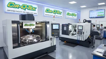
Experienced CNC providers can hold tolerances as tight as ±0.0005". Cir-Q-Tek, for instance, runs multi-axis, multi-tasking milling and turning equipment with live tooling and multiple spindles inside ISO 9001-certified, IATF 16949 and ISO 13485-aligned facilities: the kind of process control regulated industries expect from a prototype partner.
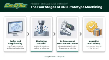
Regulation and Control: In-Process and Post-Process Checks
A machinist doesn't just program a part and walk away. In-process measurement and first-piece verification check dimensions before the full cut runs — catching a deviation on part one is far cheaper than scrapping a batch.
Post-processing steps follow the cut itself. Deburring removes sharp edges left by the cutting tool, and edge cleanup prevents handling injuries and measurement errors during inspection.
Catching a dimensional problem early avoids wasting expensive stock or losing time on an entire batch. In regulated fields like medical device and automotive manufacturing, this control isn't optional — it's built into the quality system. IATF 16949 guidance specifies that ongoing layout inspection and functional testing belong in a documented control plan, with first-off and last-off validation applied where appropriate.
Output: Inspection and Delivery
The final output is a dimensionally verified, production-intent part ready for fit checks, functional testing, or small-batch validation. The goal is a part that behaves like production hardware, because in most respects it is production hardware.
Inspection findings feed back in one of two directions:
If something doesn't fit or perform as expected, findings go back to design so revisions happen before the next iteration. If the part checks out, the same process and programming can move forward into a low-volume production run.
Using production-like materials in early testing reduces the number of surprises that show up during first-article builds later, according to ASME. That is why DFM reviews often flag material or geometry changes before a shop commits to a costly prototype cycle: catching machinability issues early prevents wasted stock and repeat setups later.
Where CNC Prototype Machining Is Used
CNC prototype machining typically enters the workflow after a design freeze and before tooling investment. It supports fit checks, functional testing, and bridge production runs: the gap between "this should work" and "this is ready for full manufacturing."
It performs best under specific conditions:
- Tight-tolerance assemblies where parts must mate precisely with other components
- Load-bearing or functional testing that needs real mechanical behavior, not an approximation
- Projects that need production-grade materials rather than a visual-only mock-up
A few sectors rely on it heavily:
- Medical devices — regulatory-grade validation and ISO 13485-aligned quality systems
- Automotive — IATF 16949 control plans that drive layout inspection and functional testing
- Telecom and electronics — one-off machined enclosures for replacement parts or new-design prototypes
- Industrial process control — gears, housings, and equipment parts that must survive real-world testing before scaling
Companies serving medical and automotive clients need certifications that match the regulatory bar, especially ISO 13485 and IATF 16949. Cir-Q-Tek's precision CNC machining operates under both certifications, which matters when a prototype is a step in a documented regulatory pathway, not just a test part.
Conclusion
CNC prototype machining works because each stage builds on the last. Programming sets the foundation, cutting shapes the part, in-process control catches deviation before it compounds, and inspection confirms the part actually meets spec. The result is a part that matches its production counterpart in both form and function.
Understanding that sequence changes how engineering teams make decisions. It leads to realistic tolerance choices, fewer redesign cycles, and a clearer sense of what to ask a machining partner before committing to a project. Working with an ISO-certified provider capable of carrying a validated prototype straight into low-volume or bridge production removes a layer of risk from that transition.
Frequently Asked Questions
What does CNC stand for?
CNC stands for Computer Numerical Control. It refers to machinery guided by pre-programmed computer software that controls tool movement with precision far beyond manual operation.
What is prototype machining?
Prototype machining produces a small batch or one-off version of a part before full production begins. Teams use it to validate design, fit, and function before investing in tooling or mass manufacturing.
How long does CNC prototype machining typically take?
Simple parts can be machined in a matter of days. Complex geometries, tight tolerances, or specialty materials extend lead time, since programming and fixturing setup usually take longer than the actual cut.
What materials can be used for CNC prototype machining?
Common metals include aluminum, stainless steel, and titanium; common plastics include ABS, Delrin, and PEEK. Material choice depends on what the prototype needs to prove — strength, weight, chemical resistance, or thermal performance.
How much does CNC prototype machining cost?
Cost depends on setup time, machine time, material, and tolerance or finish requirements. For a single prototype, setup is usually the largest cost driver, since it doesn't get spread across multiple units.
Is CNC machining better than 3D printing for prototypes?
CNC is the better choice when you need production-grade materials, tight tolerances, or functional testing under real load. 3D printing is better suited to fast visual checks or parts with complex internal geometries that cutting tools can't reach.