This guide is written for electronics engineers, procurement managers, and product designers working in medical, automotive, wearable, and telecom industries. In these fields, a cracked solder joint or a delaminated trace isn't just a scrapped board — it can mean a failed compliance audit, a recalled product, or a device that stops working inside a patient.
Flex PCB assembly comes up constantly in design reviews and sourcing conversations, yet it's often poorly understood once you get down to the manufacturing floor. This guide breaks down how the process works, what affects quality, where it commonly goes wrong, and when flex is — and isn't — the right call.
Key Takeaways
- Flex assembly mirrors rigid SMT flow, with added moisture-removal baking and rigid carrier fixturing
- Polyimide substrates and rolled annealed (RA) copper deliver flexibility and long-term bend life
- Moisture sensitivity, substrate fragility, and thermal control are the three biggest assembly challenges
- Higher cost and longer lead times stem from specialized tooling and lower component density
- A certified partner (ISO 13485, IATF 16949) significantly cuts defect risk in regulated industries
What Is Flex PCB Assembly?
Flex PCB assembly is the process of populating a bare flexible printed circuit (FPC) with electronic components—primarily through surface-mount technology—to produce a fully functional flex PCBA.
The goal is a lightweight, bendable, durable circuit assembly that fits into compact or dynamically moving spaces where a rigid board simply can't go. Think of a folded connector inside a hearing aid, or a ribbon circuit winding through a car's steering column.
Flex assembly differs from its two closest relatives:
- Rigid PCB assembly uses FR4 substrate, stays static once installed, and commonly includes through-hole components
- Rigid-flex assembly is a hybrid, combining rigid sections for component density with flexible interconnects for folding or dynamic movement in one continuous board
Why Flex PCB Assembly Is Used in Modern Electronics
Manufacturers turn to flex assembly to hit targets rigid boards can't: miniaturization, weight reduction, and 3D packaging inside increasingly cramped enclosures. The market reflects that shift. The global flexible printed circuit board market was valued at $23.8 billion in 2024 and is projected to reach $50.8 billion by 2030, a 13.7% CAGR, according to Grand View Research.

Different industries push flex adoption for different reasons:
- Medical devices need conformable, lightweight circuits that fit against or inside the body without adding bulk
- EVs and ADAS modules need circuits that survive vibration, heat cycling, and tight routing around mechanical assemblies
- Wearables need dynamic bend life, since the circuit flexes every time the wearer moves
Miss the fundamentals in any of these environments, and the same failures show up: solder joint cracking, delamination, and trace fatigue from repeated bending. These aren't rare edge cases. They're the predictable result of treating flex assembly like rigid assembly with a different substrate underneath it.
Where Flex PCB Assembly Is Applied
Flex assembly shows up across a wide range of end-use systems:
- Wearable health monitors and fitness trackers
- Implantable medical devices, including pacemakers and neurostimulators
- Automotive ADAS and EV battery or control modules
- Foldable consumer electronics
- Industrial sensors in tight or moving enclosures
It also runs through every build stage—prototypes, pilot runs, and volume production. Each unit needs the same careful handling, because flex-specific risks don't ease as quantities go up; they're baked into the design.
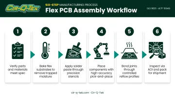
The Flex PCB Assembly Process: Step-by-Step
Flex assembly takes raw inputs (a bare FPC, bill of materials, solder paste, and components) through preparation, placement, and thermal bonding stages. Each stage is controlled by temperature, alignment tooling, and inspection checkpoints, ending in a fully populated, tested flex PCBA.
The big difference from rigid board assembly is that the flex board must be temporarily secured to a rigid carrier or pallet through most of the process. Without that support, a thin, floppy substrate warps, misaligns, or jams standard SMT equipment.
Step 1: Bill of Materials and Incoming Inspection
Before any processing starts, the BOM is finalized. Incoming FPCs and components go through visual and dimensional inspection, plus moisture-sensitivity checks. Catching a wrong copper weight or a warped panel here is far cheaper than catching it after reflow.
Step 2: Baking to Remove Moisture
Polyimide is hygroscopic: it absorbs moisture from the air. Left untreated, that trapped moisture turns to steam during reflow and causes delamination, sometimes called "popcorning."
PICA Manufacturing recommends these bake times at 105-115°C:
- Single- and double-sided FPCs: 2-3 hours
- Three-layer boards: 3-4 hours
- Four-or-more-layer constructions: at least 4 hours
Step 3: Solder Paste Printing
With the board mounted on a rigid carrier to keep it flat, solder paste is applied through a stencil using a squeegee blade. Without that carrier, the flex material would give under squeegee pressure, throwing off paste volume and alignment.
Step 4: Component Placement (Pick-and-Place)
High-speed pick-and-place machines position SMD components onto paste deposits. Flex boards often need custom nozzles, tighter vision calibration, and adjusted placement pressure, since thin or irregular substrates can shift under settings tuned for rigid boards.
Step 5: Reflow Soldering
Reflow runs through four stages:
- Preheat
- Thermal soak
- Reflow
- Cooling
Ramp rates need tight control. Heating too fast can scorch a thin substrate before the solder even melts.
Flex boards have lower thermal mass than rigid FR4, so they heat and cool faster. That makes profiling less forgiving and more dependent on real thermocouple data than a generic recipe.
Step 6: Inspection, Testing, and Final Packaging
Finished boards go through AOI and/or X-ray inspection, electrical testing, and a final quality check. They're then packaged with moisture-barrier bags or anti-static protection before shipment. The same moisture sensitivity from Step 2 applies just as much on the way out the door.
Key Factors That Affect Flex PCB Assembly Quality
Several variables determine whether a flex PCBA holds up over its intended lifespan, or fails after a few hundred bend cycles:
- Base material selection — Polyimide balances thermal resistance and flexibility for most designs; PET costs less but handles less heat; LCP fits high-frequency work where moisture stability matters
- Copper type — RA copper handles repeated flexing far better than electrodeposited copper, which has lower elongation and fractures more easily under dynamic bending
- Bend radius and layer count — Tighter radii and more layers increase mechanical stress on traces and solder joints, which tightens design limits
- Component placement relative to bend zones — Parts and solder joints inside active bend areas are the most common source of long-term failure; stiffeners protect nearby joints
- Equipment dependencies — Consistent results depend on rigid carrier fixtures, calibrated pick-and-place tooling, and a properly profiled reflow oven
As a design rule of thumb, Minco's flex design guidance recommends a bend radius of at least 10 times material thickness for reliable performance. Tighter radii need specialized forming and lower cycle-life expectations.
Common Challenges in Flex PCB Assembly and How to Solve Them
Flex assembly introduces failure modes rigid boards rarely see. Handle these six issues early and you avoid most scrap, rework, and field failures.
Moisture sensitivity. Polyimide absorbs ambient moisture. Left unbaked, that moisture flashes to steam during reflow and delaminates the board. Bake boards on a cycle scaled to thickness before assembly starts.
Handling and fixturing fragility. Thin, flimsy boards can't run through a standard SMT conveyor unassisted — they jam, warp, or drift out of alignment. Tape or vacuum-mount the board to a rigid carrier pallet through printing and placement.
Thermal profiling difficulty. Flex boards have lower thermal mass than rigid FR4, so they heat up (and scorch) faster. Use a calibrated reflow profile with controlled ramp rates, verified against real thermocouple data.
Stress concentration at bend regions. Components or solder joints placed too close to a flex zone crack under repeated bending. Route traces with gentle curves instead of sharp angles, and keep stiffeners away from active bend areas.
Cost-and-timeline misconceptions. Some teams assume flex assembly will mirror rigid PCB pricing and lead times. It won't. Flex requires specialized tooling, trained staff, and tighter environmental controls, so expect higher per-unit cost and longer lead times than an equivalent rigid board.
Misreading inspection results. A board that passes AOI isn't automatically reliable long-term. AOI catches placement and solder defects at a single point in time; it says nothing about how the board holds up after thousands of bend cycles. Flex-specific stress testing and bend-cycle validation close that gap.
Choosing the Right Flex PCB Assembly Partner
Flex isn't always the right answer. For simple, static, cost-sensitive high-volume consumer products, a rigid board often does the same job for less money. Choosing flex purely for aesthetics or "future-proofing," rather than a genuine mechanical or space requirement, adds cost and complexity without a real payoff.
When flex genuinely is needed, especially for regulated products, the manufacturing partner matters as much as the design. Look for:
- Certifications matching your industry: ISO 13485 for medical devices, IATF 16949 for automotive, ISO 9001 as a baseline
- Inline inspection (AOI and X-ray) built into the SMT line, not bolted on as an afterthought
- Proven fine-pitch placement capability for the small, dense components common in flex designs
- Realistic quick-turn prototyping, so design issues surface before a full production run
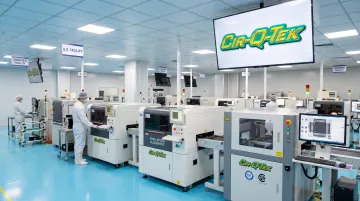
Cir-Q-Tek fits this profile for teams sourcing flex PCB and PCBA work. The company holds ISO 9001, ISO 13485, and IATF 16949 certifications. Its SMT lines run inline AOI and X-ray inspection, with placement capability down to 01005 passives and BGA packages spaced at 0.2mm—fine-pitch work common in flex designs.
Its dual U.S.-Shenzhen model pairs Shenzhen manufacturing speed and quick-turn prototypes (built in as little as three business days) with a second quality inspection at its Bristol, Pennsylvania facility before anything ships. That gives procurement teams a domestic checkpoint on offshore-priced production, rather than having to take an overseas factory's word for it.
Understanding how the process works, what drives its cost, and where it typically fails matters more than defaulting to flex circuitry because it looks modern. Get the fundamentals right, or work with a partner who already has, and flex assembly delivers exactly what it promises: a durable, compact circuit that fits where a rigid board never could.
Frequently Asked Questions
What components are used in flex PCB assembly?
Flex PCB assembly relies almost entirely on SMDs: resistors, capacitors, ICs, and ultra-miniature packages. Through-hole components are rarely used. Structural elements like polyimide substrates, RA copper traces, coverlays, and stiffeners complete the build.
Can you put components on a flex PCB?
Yes. Components are mounted with SMT while the board is held on a rigid carrier pallet, then soldered with a tightly controlled reflow profile.
What is the difference between FPC and PCBA?
FPC refers to the bare, unpopulated flexible circuit board. Flex PCBA is the finished assembly: the same board after components have been soldered onto it.
How do you attach components to a flexible circuit?
The core sequence is: bake to remove moisture, mount on a rigid pallet, print solder paste, place components, then run a controlled reflow profile.
What is the minimum bend radius for flex PCB assembly?
It depends on whether the application is static or dynamic, but typical guidance ranges from roughly 6-10 times board thickness for single/double-sided flex up to 20 times for multilayer builds. RA copper improves flex life at any radius.
What certifications should a flex PCB assembly supplier have for regulated industries?
Look for ISO 13485 for medical, IATF 16949 for automotive, ISO 9001 as a baseline QMS, and UL/cUL approval, with inspection performed to IPC-A-610 standards.